Please specify the quantity of product(s).


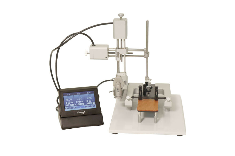
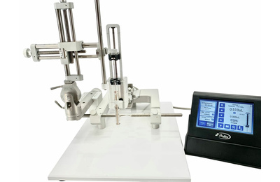
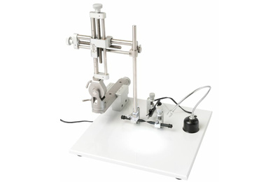
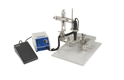
Stoelting Motorized Lab Standard Stereotaxic Instrument
| Item | Product | Price | QTY |
|---|---|---|---|
| 51600M | Motorized Lab Standard Stereotaxic, Rat w/Joystick | Login | |
| 51615M | Motorized Lab Standard w/Mouse & Neonates Adaptor w/Joystick | Login | |
| 51670M | Motorized Lab Standard, Rat and Mouse w/Joystick | Login | |
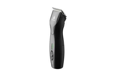
| 51555M | Micromotor Drill w/LED Lights & Bits (Motorized & QSI only) | Login | |
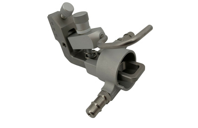
| 51604MOT | Motorized Manipulator Arm, 3 Axes, Standard LEFT | Login | |
| 51606MOT | Motorized Manipulator Arm, 3 Axes, Standard, RIGHT | Login | |
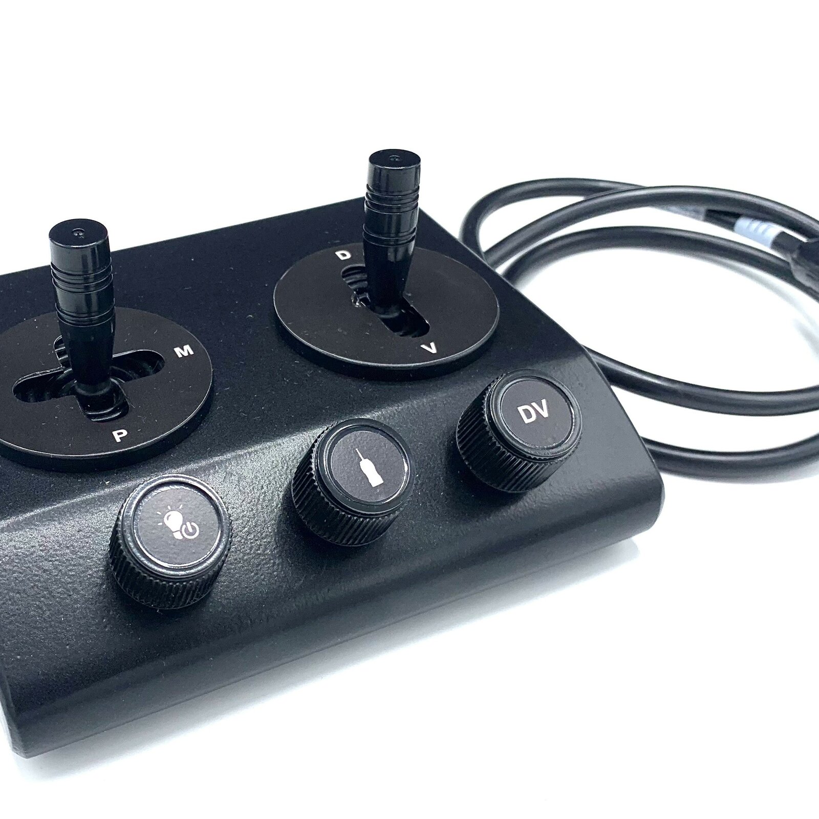
| 52702 | Joystick for Motorized Control Box | Login |
The Classic Lab Standard™ Stereotaxic Instrument has been a standard in research labs for nearly five decades. The time-proven 'U'-Frame design provides stability and adaptability while the instrument's exclusive, triple-lead screws allow for smooth, consistent movements with rapid positioning. This Classic Lab Standard™ includes Stoelting’s Motorized Stereotaxic Manipulator Arms which are designed for fast, accurate positioning during stereotaxic surgery. Ideal for inexperienced users, the motorized manipulator arms employ a touchscreen display for easy-to-control movement of each axis. Manual movement is available anytime. Optional Drill feature available.
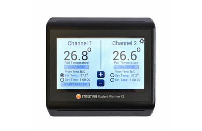
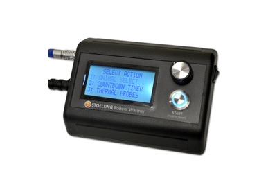
Warmer Ready Base: Stoelting Stereotaxic Instruments are the ONLY stereotaxic instrument on the market with an integrated warming base included on all units! Simply purchase Stoelting’s Rodent Warmer Control Box X1 (item 53800), or Rodent Warmer Control Box X2 (item 53850) to use the warming function.
Stoelting’s Motorized Stereotaxic Manipulator Arms are designed for fast, accurate positioning during stereotaxic surgery. Ideal for inexperienced users, the motorized manipulator arms employ a touchscreen display for easy-to-control movement of each axis. Manual movement is available anytime. Optional Drill feature available (51555M).
Stoelting's Motorized Manipulator Arm Features:
• Automatic motorized movement using the touchscreen display
• Various speeds (4mm/s to 0.1mm/s)
• Manual option always available
• Optional Drill feature
• 10µm movement
Electrical Specs:
Power Supply:
Part Number: SD165-24-UD-P5
Input: 100 – 240V – 50 – 60 HZ 1.4A Max
Output : 24V 2.71A
Approvals : CE, FCC, cULus, ROHS, GS, PSE
LCD Screen Size:
Resolution: 480x272
Color: Full Color
Touch: Resistive touch
Motors:
3 high-performance stepper Motors
Resolution: .1 microns.
Routing Offset: 0.05 microns
Maximum Speed: 2.7mm/s
Minimum Speed: 15um/s *D-V Only*
Calibrating Screen:
The screen may become un-calibrated during shipping or over time.
When to Calibrate the Screen:
- If the buttons are not responding
- If the screen does not respond to pressing buttons
- If you have to press down with a lot of pressure
To Calibrate the Screen:
- Turn off power
- Press down on the screen with figure anywhere while power if off
- With the finger pressing down on the screen turn on the power
During bootup, the screen detects the PRESS and goes into calibration mode. During Calibration the screen will display blinking dots one at a time. Press the MIDDLE of each dot as they appear. Be careful to make sure you press the middle of each dot. The screen will go through Calibration 2 times and when complete the screen will return to the home screen. If you find the calibration unsatisfactory you can always repeat the calibration.
Stoelting's Motorized Manipulator Arm Features:
• Automatic motorized movement using the touchscreen display
• Various speeds (4mm/s to 0.1mm/s)
• Manual option always available
• Optional Drill feature
• 10µm movement
Motor Speeds:
|
Motor Speeds |
A-P |
M-L |
D-V |
Pause |
|
*2.77 mm/s |
YES |
YES |
YES |
NO |
|
*1 mm/s |
YES |
YES |
YES |
NO |
|
.5 mm/s |
NO |
NO |
YES |
YES |
|
250um/s |
NO |
NO |
YES |
YES |
|
160 um/s |
YES |
YES |
NO |
YES |
|
100 um/s |
NO |
NO |
YES |
YES |
|
75 um/s |
NO |
NO |
YES |
YES |
|
50 um/s |
NO |
NO |
YES |
YES |
|
25 um/s |
NO |
NO |
YES |
YES |
|
15 um/s |
NO |
NO |
YES |
YES |
Note: * Pause is not an option for speeds highlighted in RED.
Note: These speeds are approximations and will vary a little.
Terms Defined:
A-P = Anterior – Posterior Axis Coordinate
M-L = Medial – Lateral Axis Coordinate
D_V = Dorsal-Ventral Axis Coordinate
Bregma = The junction of the sagittal and coronal sutures at the top of the skull (www.freedictionary.com)
Home = Zero Point of reference
Saved Offset = Distance Value added to axis position when play button is pressed or when Routing mode is engaged.
Routing Resolution = This is the distance the drill will travel each pass until it reaches the D-V offset. The routing resolution is 0.05mm each route.
Routing:
The routing feature is used to cut out a piece of the skull. The D-V routing distance is .05mm each step. This means that if D-V routing offset is .10mm it will take 2 passes to complete the route.
Steps:
1: Move the drill to the start position of the routing
2: Press the Keypad button for the A-P.
A: Press the Clear button
B: Type in the offset amount
C: Press the Save button
D: Press the Hide button.
3: Press the M-L button
A: Press the Clear Button
B: Type in the offset amount
C: Press the Save Button
D: Press the Hide Button
4: Press the D-V Button
A: Press the Clear Button
B: Type in the offset amount – about .20mm to start
C: Press the save button
5: Turn on Drill by pressing the drill button
6: Set the speed for each axis.
7: Press the Route button.
